What to expect
Finish, tolerances and design rules
Manufactured parts carry the marks of the process that made them. The characteristics below are inherent to that process and are not defects. Please review before ordering.
Expected finish characteristics
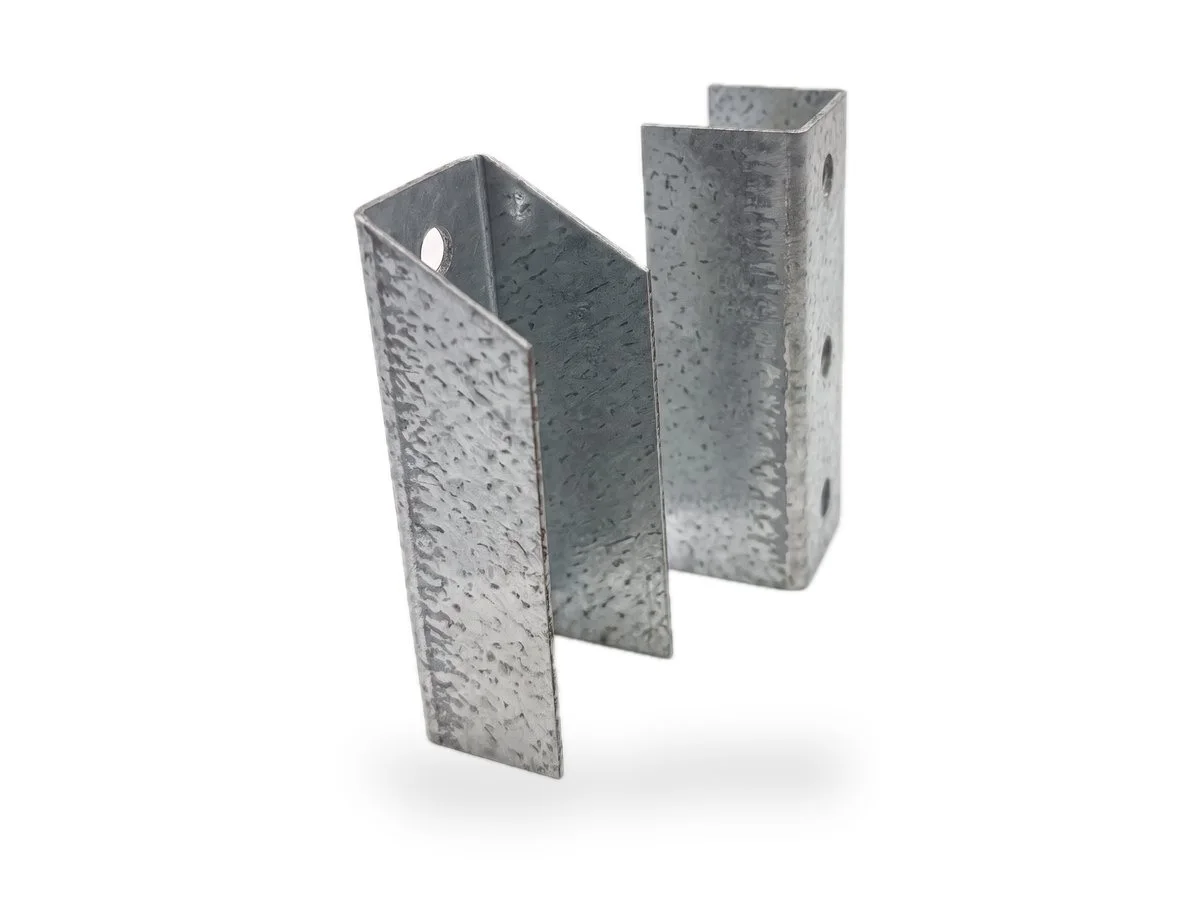
Witness marks on bends
Press brake tooling leaves a faint line on the outside of every bend. Every press brake does. It is not damage and does not weaken the part.
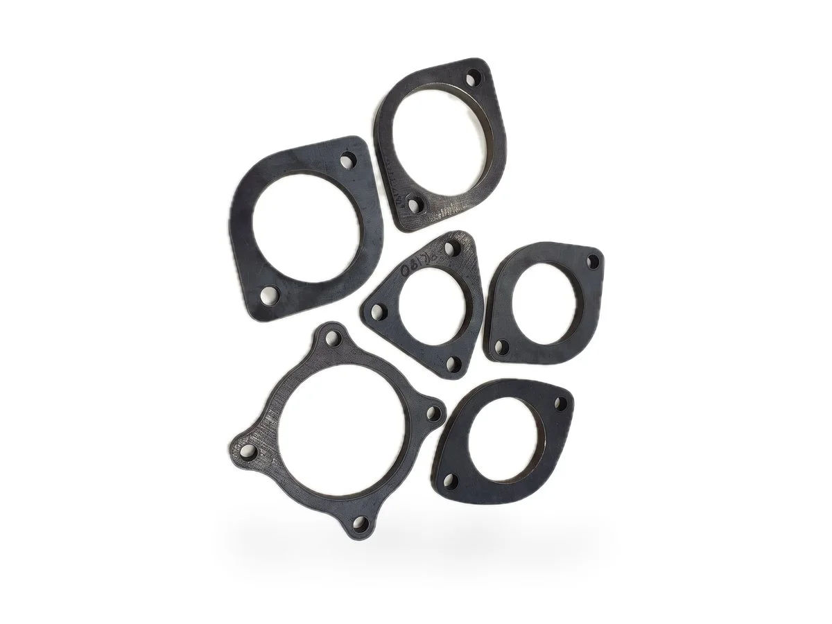
Laser cut edges
A cut edge can show a potential micro burr or a witness line where the cut started and finished.
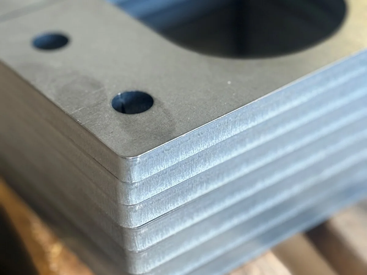
Sharp edges as standard
Parts are supplied as cut. Without edge rounding, cut edges remain square and could have a micro burr. Add edge rounding at the quote stage if required.
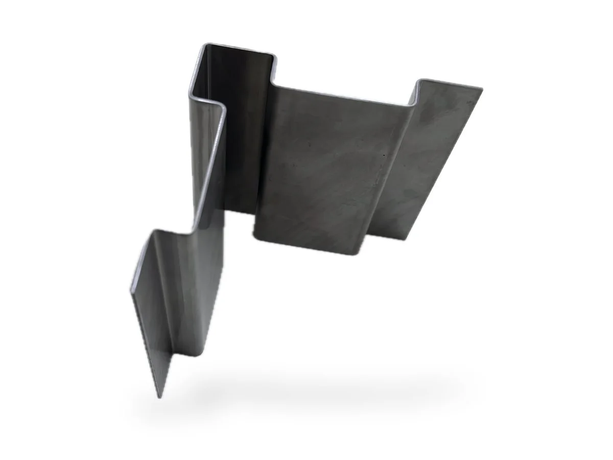
Mill finish on the material
Sheet arrives from the mill with its own mill finish, handling marks, minor scratches or protective film. Raw sheet is not a cosmetic product.
Bulging at the ends of a bend
Material has to go somewhere when it folds, so it pushes out slightly at each end of the bend line. You will see a small swelling on the edges either side. It is the metal behaving normally under the press brake and it does not affect how the part fits or performs.
Bright edges on galvanised
The laser burns the zinc back where it cuts, so a galvanised part arrives with a bare steel line around every cut edge and hole. That line will surface rust before the coated faces do. It is unavoidable on cut galvanised sheet. If the part lives outdoors and you need full coverage, have it galvanised after cutting rather than cut from pre-galvanised stock.
Holes and slots near a bend pull out of shape
Metal stretches around the outside of a fold. Anything sitting inside roughly two and a half times the material thickness of the bend line gets dragged with it, so a round hole comes out slightly oval. Move the feature further from the bend, add a relief slot, or leave it out and drill after folding.
Tolerances
Cutting tolerance
One figure, whatever the material and thickness.
Cutting tolerance
±0.2 mm
Applies across every material and thickness we cut.
General design rules
T is your material thickness. Parts designed to these rules go straight to the machine without further consultation.
| Rule | Value |
|---|---|
| Minimum hole diameter | 1 x T |
| Minimum feature size | 1 x T |
| Minimum hole to edge | 1.5 x T (1 x T absolute minimum) |
| Minimum hole to bend | 2.5 x T plus the inside bend radius |
| Minimum internal bend radius | 1 x T mild steel and stainless, 1.5 to 2 x T aluminium |
| Minimum flange length | 4 x T |
| Bend angle tolerance | ±1° |
Notes on the less obvious rules
Hole to bend
Holes closer than this stretch into ovals when the part is formed. If you need them tighter, either cut a relief slot or leave the hole out and drill after bending.
Bend radius and flange length
Both are set by the V-die. The die opening runs 6 to 8 times material thickness, and the minimum flange is roughly half to two thirds of that opening, which lands at about 4 x T. Shorter flanges slip into the die and will not form.
Aluminium
Harder grades crack at tight radii, so aluminium wants a more generous inside radius than steel. 5052 forms more reliably than the stiffer grades if your part has tight bends.
Stacking bends
Angle tolerance is per bend, and a linear tolerance of roughly ±0.2 to ±0.5 mm applies to each bent dimension. Errors add up across multiple bends, so allow for it on a part with several folds.
General guidance for design work. If your part has a critical dimension, advise us before ordering and we will confirm the tolerance we can hold on that material and thickness.
Files
File requirements
- DXF and DWG are ideal. STEP for 3D parts we unfold for you. A clean vector PDF also works.
- Draw in millimetres. Every dimension, every drawing.
- Use closed contours. Open paths, duplicate lines and stray geometry get cleaned up automatically, but a clean file quotes more accurately.
- Send the flat pattern, or the 3D. For cut-only parts send the flat. If you want bends, send the 3D file and let us unfold it rather than guessing bend allowances.
- Outline your text. Convert text and logos to outlines, or put them on their own layer.
- Allow for kerf. The laser removes material as it cuts. Parts that must fit together need clearance designed in.